CONTACT & STAFF
Facility Tel.: +55 19 3512 1142
Facility E-mail: mogno@lnls.br
Coordination: Nathaly L. Archilha
Tel.: +55 19 3512 1281
E-mail: nathaly.archilha@lnls.br
Click here for more information on this Facility team.


MOGNO was designed to be a world-leading high-brilliance micro- and nano-imaging beamline using quasi-monochromatic (ΔE/E approx. 10-2) tender (22 and 39 keV) and hard (67.5 keV) X-rays, in a cone-beam geometry. This design is optimized for continuous zoom tomography (i.e. continuous magnification of the image), where the same specimen can be studied at low and high-resolution. The field of view also varies, from hundreds of micrometers, for the high resolution, up to dozens of milimeters for the low resolution. MOGNO will also be dedicated to 4D (time-resolved) imaging through in-situ experiments. The beamline will potentially attend different areas, such as geological, biological, material, earth/planetary, agriculture, and food sciences, as well as civil engineering, bioengineering, paper and wood research, chemistry, paleontology, archeology, and cultural heritage.
The advantages of X-ray tomography using a high brightness synchrotron light source are better image contrast and greater spatial and temporal resolution. In addition, the small beam bandwidth (< 1 keV, for all energies) reduces undesirable effects, such as beam hardening, and improves the quality of the data for some quantitative analysis, such as the density determination. The detection of micrometer scale characteristics in millimeter-sized samples has been somewhat routine in many X-ray tomography beamlines around the world. Notwithstanding, Mogno beamline shifted to higher energies and a nanofocus, making possible the study of high density and/or large samples with nanometric resolution (local tomography) and low dose.
The optical system of this beamline was optimized for high flux in high energies, with a small bandwidth. After the front-end, the first optical element is an horizontal elliptical mirror designed to collect the radiation from the BC, which is collimated by its sagittal curvature. The second optical system consists of Kirkpatrick–Baez (KB) mirror system coated with a ML, which selects the energies and focalizes the beam in a 100 x 100 nm2 spot. Position of both sample and detector can be adjusted to measure in a chosen magnification and image regime required by the experiment. Various detector systems based either on direct detection, such as Medipix, or indirect detection such as CCDs will be available, covering FOVs from 0.08 x 0.08 to 85 x 85 mm2, and resolutions of the order of 0.13 x 0.13 to 52 x 52 μm2.
Facility Tel.: +55 19 3512 1142
Facility E-mail: mogno@lnls.br
Coordination: Nathaly L. Archilha
Tel.: +55 19 3512 1281
E-mail: nathaly.archilha@lnls.br
Click here for more information on this Facility team.
(Submission deadline: March 8, 2026)
⚠ In this call, both experimental stations, the microstation and the nanostation, will be open for proposal submission. The specific configurations available for each experiment can be found at: https://lnls.cnpem.br/users/, under the “Available Experimental Configuration” section.
The nanostation is open for regular calls, with four experimental configurations available. Regardless of the selected experiment, the following general conditions apply:
The microstation is also open for regular calls, with two experimental configurations available. The general conditions are:
Below is important information to help you plan your experiments and increase the likelihood of a successful proposal.
Sample types and environments:
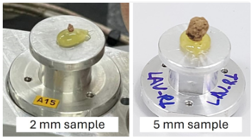
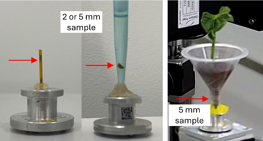
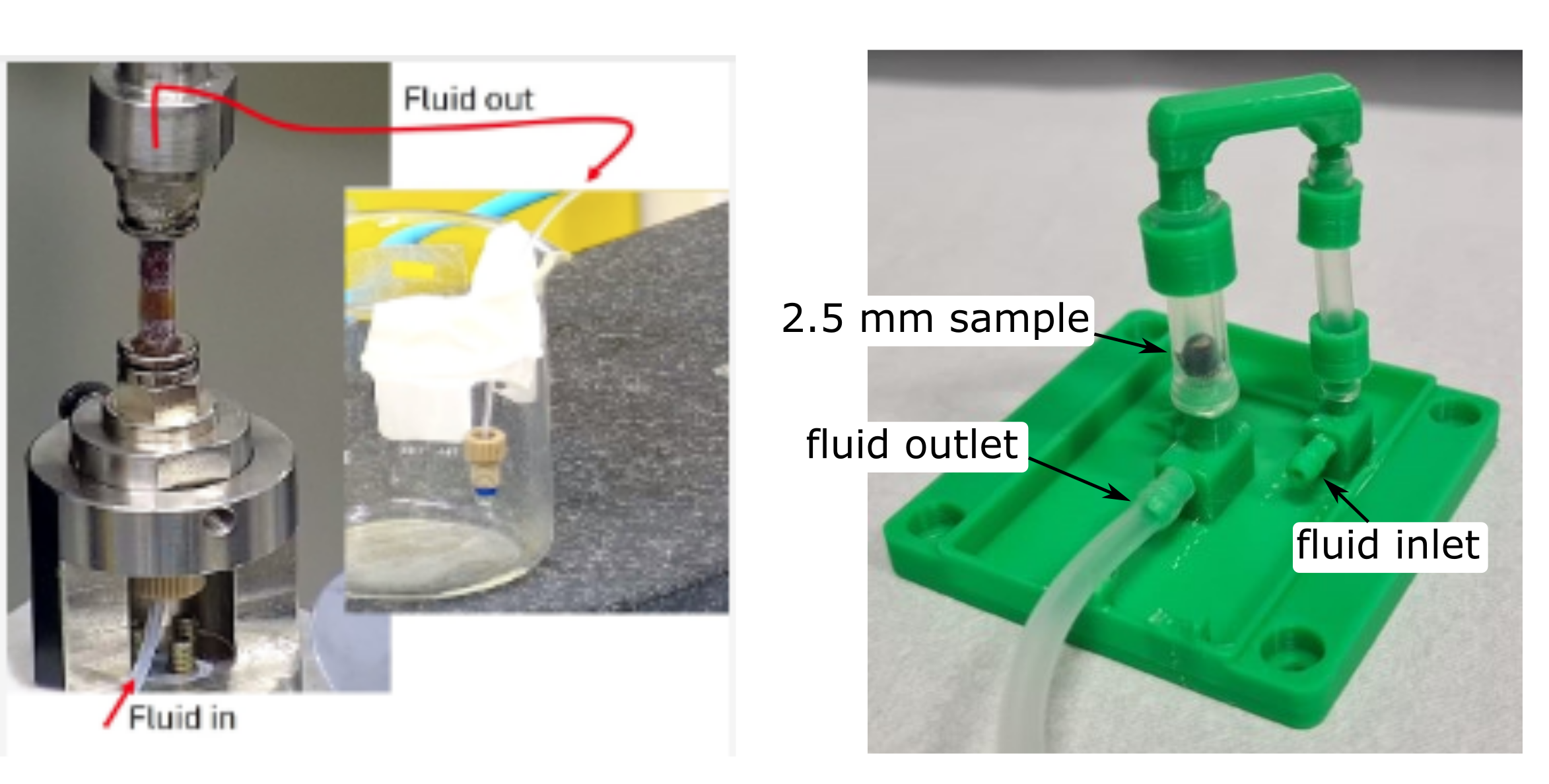
Important:
– All parameters related to flow experiments in porous media must be validated beforehand through bench tests conducted under conditions similar to those expected at the beamline. If you wish to reproduce the sample environments in your laboratory, the design files can be provided upon request. The model shown on the right is the simplest to replicate, as it is 3D-printed (resin).
– For experiments involving sample environments, at least one team member must be present at the beamline throughout the entire experiment to ensure equipment safety and proper operation. It is recommended that at least one member of the team arrives one day before the experiment begins to prepare the setup.
Figure 1 presents the optical design of MOGNO beamline. The primary source of MOGNO is a 3.2 T superbend, a permanent dipole that generates hard X-rays with critical energy of 19.15 keV and beam size of 22.1 x 8.5 mm2 (HxV, rms). MOGNO optical concept is based on a set of elliptical mirrors, the first one being a total reflection horizontal focusing mirror, which demagnifies the X-ray beam and counterbalance the horizontal inhomogeneity caused by the KB system, the second optical elements of MOGNO beamline. The KB system is composed by two multilayer mirrors, which focus the X-ray beam on both directions, down to a nanometric spot size of ~100 x 100 nm2, and also delivers three different energies: 22, 39 and 67.5 keV – simulated photon flux and energy resolution are presented in Table 1. Such high demagnification implies in a divergent beam (~3.1 mrad in both directions), and so, MOGNO beamline will operate in a cone beam geometry.
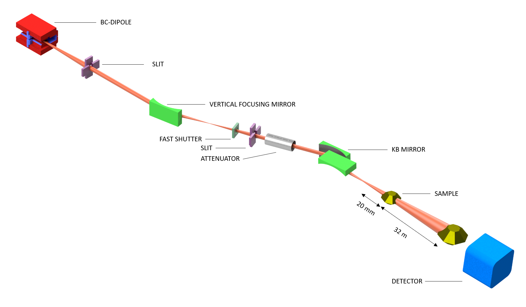
Figure 2 shows (a) an overview of the optical and experimental hutch of MOGNO beamline. The optical hutch is located on the ground represented in red, followed by the experimental hutch (approx. 30 m long), from the KB chamber to the PiMega detector stage. All mirror supports and the nanostation are based on a set of wedge shaped granite tables, designed to have three degrees of freedom (x, y and z) and all the movements are based on air bearings. The nanostation is shown in brown and three detectors serve this station: Mobipix (high-Z CdTe sensor), PiMega (Si sensor) and the PCO.edge 4.2 (sCMOS + scintillator). Next, the microstation is represented by the external gray rail. This station is composed by a set of conventional X-ray tomography stages and only the PiMega serves this experimental station. Note that there is an overlap between the two experimental stations, which covers FOVs between 3 and 18.4 mm. The side view of the front end and optical hutch is presented in (b), the nanostation in (c) and the microstaion in (d).
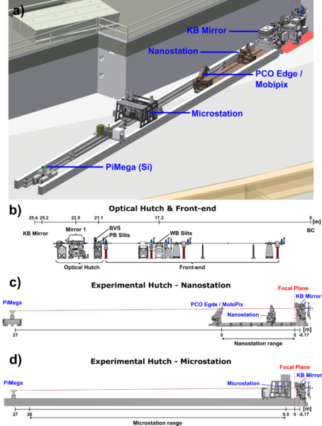
Figure 2. MOGNO beamline layout. a) Overview of the optical and experimental hutch; b) Side view of the front-end and the optical hutch. The experimental hutch has two stations: c) the nanostation, and d) the microstation. BVS: beam visualization system; PB: pink beam; WB: white beam; BC: magnet dipole BC.
Table 1 presents the elements that comprehends the front end and optical hutch and their respective functions.
| Element | Type | Position [m] | Description |
|---|---|---|---|
| Source | BM | Bending Magnet | |
| Slit | Front-end Slit | 17.200 | Limits Beamline Acceptance |
| Slit | Pink Slit | 21.133 | Defines Angular Aperture |
| MOG-1-ME | Mirror | 22.500 | Horizontal Focusing |
| Focused beam | Secondary Source | 22.875 | First Mirror Horizontal Focus |
| MOG-2-KB-HFM | Mirror | 25.175 | KB – Horizontal Focusing |
| MOG-3-KB-VFM | Mirror | 25.445 | KB – Vertical Focusing |
| Focused beam | MOGNO Source | 25.735 | MOGNO nanofocus |
Table 1 presents the elements that comprehends the front end and optical hutch and their respective functions.
Table 2 shows detailed information regarding the available energies at MOGNO beamline. All the three energies are selected by the ML, as a result of the high intensity diffraction outcome of first, second and third harmonics.
Table 2. Energy resolution, beam size and divergence on focal position and total flux for MOGNO beamline.
| Parameter | Value 1 | Value 2 | Value 3 |
|---|---|---|---|
| Central Energy [keV] | 22 | 39 | 67.5 |
| Stripe (Harmonic) | 1(1) | 1(2) | 2(1) |
| Source Spectral Flux [ph/s/0.1%b.w./100mA] |
7.4×10⁹ | 5.0×10⁹ | 1.8×10⁹ |
| Energy Bandwidth [eV] | 2840 | 940 | 720 |
| Sample Flux [ph/s/100mA] | 8.9×10¹¹ | 9.3×10¹⁰ | 1.8×10¹⁰ |
| Flux Density* [ph/s/px/100mA] | 3.8×10⁵ | 3.9×10⁴ | 2.6×10⁴ |
| Beam Size [nm] | 94×90 | 89×87 | 86×87 |
| Beam Divergence [mrad] | 3.0×3.2 | 3.0×3.2 | 3.0×3.2 |
*Detector: Pimega
Table 3 presents the available detection system at MOGNO beamline.
Table 3. Available detection system at MOGNO beamline. FOV: Field of View
| Instrument | Type | Model | Manufacturer | Specifications |
|---|---|---|---|
| Detector | sCMOS – based | PCO Edge 4.2 | 2048 x 2048 pixels Pixel size = 6.5 x 6.5 µm2 |
| Microscope | White beam Microscope with multiple lenses | Optique Peter | 2x: Pixel size = 3.612µm2, FOV= 7.402mm2 *5x: Pixel size = 1.44²µm2, FOV= 2.962mm2 *10x: Pixel size = 0.72²µm2, FOV= 1.482mm2 |
| Scintillator | LuAg:Ce | Crytur | Thickness = 5, 20, 100 µm |
| Detector | Direct detection | Mobpix (CdTe) LNLS/PiTec | 512 x 512 pixels Pixel size = 55 x 55 µm2 FOV = 28 mm x 28 mm |
| Detector | Direct detection | Pimega (Si)** LNLS/PiTec | 1536 x 1536 pixels Pixel size = 55 x 55 µm2, FOV = 80 mm x 80 mm |
* The objectives 5x and 10x are also available, but there is no significant gain in terms of resolution and the FOV is significantly decreased.
** The ideal sensor for MOGNO’s energies is a CdTe-based detector (project in progress).
Table 3 presents some of the most relevant experimental parameters for planning future experiments at MOGNO.
Table 3. MOGNO Main Experiments
| Requirement | Nano-tomography | Micro-tomography | 4D micro-tomography |
|---|---|---|---|
| Use case | Dry samples, < 0.5 kg under contactless furnace or cryo stream cooling from the top | Dry samples, or live animals (in-vivo tomog.) with air and anesthetic supply (< 0.5 kg) | Special condition samples (flow cell) 5 mm wide, with oil flow (100-200 psi) |
| Maximum Resolution | 100 nm | 500 nm | > 0.5 µm @ 1 Hz, > 1 µm @ 10 Hz |
| Beam size at sample | 50 µm (min) | 500 µm (min) | 1 mm (min) |
| Average scan time | 5 seconds/tomo | 500 milliseconds/tomo | 30 milliseconds/tomo |
| Average throughput*** | 30 tomographies/hour | 60 tomographies/hour | 20 tomographies/seconds |
| Max sample load | 0.5 kg | 2 kg | 2 kg |
| Sample width** | < 80 mm | < 80 mm | < 8 mm |
* Same sample, under in-situ experimental conditions.
** Special samples, i.e. cryogenic samples, have limited size < 16 mm.
*** Limited by sample loading and alignment.
At MOGNO beamline, the sample can move along the Z axis from the X-ray secondary source (KB system’s focus) up to the detector (Pimega) position, which will be fixed 27.5 m downstream (Fig. 3). In a cone-beam system like MOGNO’s, the resulting geometrical resolution (σR) is a function of the source size (σs), the pixel size of the detector (σD), and local magnification (m) which, in turn, depends on the source-to-sample (Z1) and sample-to-detector (Z2) distances (Table 3, Fig. 3), according to the following relations (Bartels, 2013; Krenkel et al., 2015):
$$ \sigma_R = \sqrt{\left( 1-\frac{1}{m}\right)^2 \sigma_S^2 + \frac{1}{m^2}\sigma_D^2} $$
where m = 1 + Z2/Z1, and σD/m is the effective pixel size (σeff).
In addition to σR and m, the field of view at sample (FOVS) also varies depending on the sample position in Z axis (FOVS= σeff * number of pixels) (Fig. 4). The continuous magnification of the image allowed by this design – from dozens of micrometers to hundreds of nanometers – will be exploited to image samples in different resolutions, in a true non-destructive way (no need of resizing the samples), and this is known as zoom-tomography. The beamline will count on a microstation, devoted to more complex setups that might cause a certain level of vibration, and a nanostation dedicated to simpler setups due to more rigorous requirements of stability to achieve the higher image resolutions. Besides acquiring a single local tomography, with high image resolution (e.g. FOVS = 77 um and σR = 130 nm), from a volume of interest of a sample that is larger than the FOVS, it will also be possible to acquire multiple neighboring local tomographies with the same σR, aiming to generate a final panoramic tomography (e.g., three neighboring local tomographies making a total FOVS = 225 µm with no significative impact on image resolution). The zoom-tomography capability of MOGNO will be especially important for studies of hierarchical materials that often present properties varying across scales and, thus, require investigations focused on the upscaling of findings and solutions.
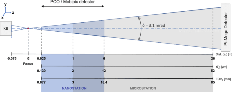
Figure 3. Optical magnification layout. Micro and nanostation magnification limits. Notes: Z1: distance source-sample; σR: geometrical resolution; FOVS: field of view at sample.
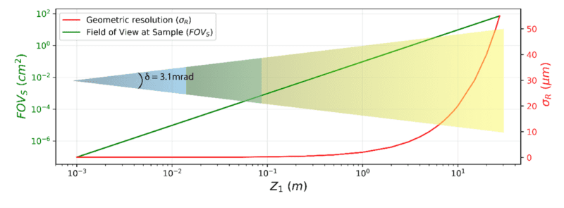
Figure 4. Relationship between the field of view at sample (FOVS), the geometrical resolution (σR), and the source-to-sample distance (Z1), along the experimental stations. The numbers are related to the PiMega detector.
MOGNO’s flexible design will allow different contrast imaging. The absorption contrast imaging is based on differences in the X-ray absorption by different materials in a given sample and will be predominant in micrometric resolutions. On the other hand, increasing the spatial resolution and lowering the energy leads to the phase-contrast imaging, based on the X-ray wave refraction followed by free-space propagation. The absorption and phase-contrast imaging occur in the so-called contact and far to near field image regimes, respectively (Bartels, 2013). Phase-contrast imaging will benefit measurements of biological samples (Cloetens et al., 1999; Momose et al., 1996) or biological structures inside an inorganic matrix (Carrel et al., 2017), which present low X-ray attenuation particularly at high energies.
The high X-ray flux at MOGNO will allow to perform an experiment (i.e. collect data to reconstruct a 3D image of the sample) in a short time frame, around a few seconds [3]. Due to this characteristic, 3D imaging competences can be extended to 4D (time-resolved) imaging through in-situ/in-vivo experiments. Particularly, the combination of high X-ray flux and high energy at MOGNO enables 4D measurements of hierarchical samples, such as rocks and soils. Fast imaging provides more detailed fundamental understanding of several dynamical processes, such as fluid flow in porous media (Pak et al., 2020), material responses during mechanical, thermal, or chemical loadings (Kudrna Prašek et al., 2018; Yoshinaka et al., 2019), and in in-vivo condition for small rodents (Bayat et al., 2020). In porous media related investigations, such rigorous studies open the way for upscaling the results from the pore to field scale (Archilha et al., 2016; Lucas et al., 2020). In parallel, in vivo measurements of small animals (e.g. mouse) can help in the evaluation of the effects of biomaterials implantation on bone structure, growth, osteointegration and degradation/resorption of these materials. To tackle the broad applications of 4D measurements, specific environmental cells that mimic real conditions, e.g. controlled pressure, temperature and flow rates, are required. These cells and all the necessary structure are under development to ensure the system’s compatibility with the beamline and users can count on the MOGNO team to help developing new environmental cells.
One of the main interests in tissue bioengineering is to understand how the microstructure of the trabecular bone adapts to mechanical loads, especially in the bone repair process. Understanding these aspects can promote strategies for developing new materials capable of acting as a bone graft substitute without interfering with the formation of the tissue’s original architecture, thus preserving its intrinsic mechanical resistance. Through X-ray microtomography based on synchrotron radiation (SR-uCT), Martinez-Zelaya et al. explored the 3D microarchitecture of the newly formed trabecular tissue in the cortical region of a rat tibia defect, in the absence and the presence of carbonated hydroxyapatite/alginate (cHA) microspheres. This study provides the first evidence that the trabecular meshwork formed during the bone repair process presents a well-organized 3D microarchitecture consisting of nodes with 3, 4, and 5 trabecular junctions. Another study model is the calvaria defect, where it is possible to study the so-called critical defects. In this model, Schneider et al. showed that cHA microspheres loaded with rhBMP have a high tissue repair efficiency. By SR-uCT measurements, the authors propose that the thickness of the new-formed tissue describes an exponential decay behavior, varying with the distance from the reference point to the edge of the defect.
Micro-computed tomography (µCT) is one of the most used non-destructive imaging techniques in biomedical research for volumetric visualization of tissue or even cell morphology. µCT using synchrotron radiation (SR-µCT) offers the highest photon flux and the best signal-to-noise ratio, which increases the resolution for cell scales. Additionally, a considerably narrower bandwidth remains the deposited dose and, consequently, the damage by ionizing radiation. This allows for multiple measurements in the same local sample, which are combined into a single large volume, generating single-cell details in whole organs of small animals [1]. These data are crucial for research in the areas of human health, especially cardiovascular and neurosciences in which tissue architecture modeling helps to understand the morphological changes and hierarchical organization of cells in the context of health and disease.
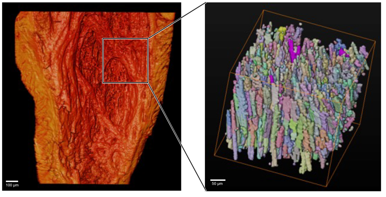
Figure: 3D rendering of a synchrotron microtomography of the ventricular region of a mouse heart (left) with detail of a local tomography with cell resolution for histoarchitecture studies (right).
New developments that seek to improve crop production are highly relevant to the Brazilian economy, which considerably depends on Agriculture, and to ensure food security. In this context, above and below ground factors that impact crop growth have been on the spotlight of many research works. For instance, by applying X-ray spectroscopy and XCT, Duran et al. (2018) showed that coated iron nanoparticles can penetrate within the structure of Phaseolus vulgaris (common bean) seeds and enhance the seedling development. In another investigation, Negrão et al. (2018) applied XCT and XRF to analyze the variability of inorganic contents in agricultural residues such as sugar cane bagasse and straw, which are valuable resources for bioenergy and biorefining. In turn, Ferreira et al. (2019) showed that liming, a common practice to alleviate soil acidity, affected important soil physical parameters at the aggregate scale (e.g. decrease in total porosity and increase in tortuosity of pores), indicating reduced efficiency of air and water flow in the interior of such soil aggregates.
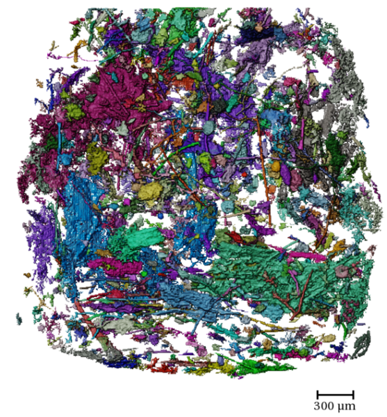
Figure: 3D rendering of the pore space of a soil aggregate, where different colors represent individual pores (i.e., not connected to each other).
Human history is deeply interconnected with plant use for several purposes (ex. food and medicines). Archeobotany is the subarea of Archeology that studies vegetal remains preserved in archeological sites to understand the relationship of ancient human populations with the utilization of plants. However, in many cases researchers need to use destructive methods to the identification and interpretation of these materials, such as the production of histological slides. In this sense, Synchrotron Radiation MicroCT presents itself as a powerful non-destructive technique to the investigation of archeobotanical samples. In a recent study, Calo and colleagues (2020) demonstrated the potencial of this technique in comparison with more traditional methods. These authors investigated drupes (type of fruit similar to peaches) recovered from an archeological site in the Brazilian Amazon within a stratigraphic sequence that can be as old as 6000 years BP. The microtomographic analysis was able to show several important morphological structures in these fruits, such as the pericarp, mesocarp, endocarp, seed-embryo and cellular structures. Besides, the authors demonstrated that this technique has a great advantage in the obtention of accurate volumetric measurements. Thus, the use of Synchrotron Radiation MicroCT may provide new methodologies to the construction of a new database for the identification of plant remains from archeological sites.
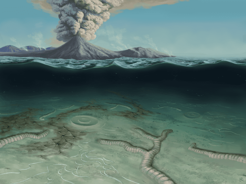
The history of life on Earth is told by the fossils. Yet, the processes that lead to fossilization depend on specific conditions within the sedimentary environment, even more if the organisms lack hard parts. The Ediacaran Period (635 Ma–539 Ma) marks the time in the geological record where the first complex macroscopic biota appeared, which is now exceptionally preserved in rocks of this age around the world. The processes that led to the fossilization of these organisms are still poorly understood, but a recent study using Synchrotron Radiation MicroCT showed that the Ediacaran biota from the South of Brazil may have been preserved in clay-rich sediments. These clays would have been originated by the rapid alteration of volcanogenic sediments associated with the fossils, a situation analogous to what occurred in Pompeii due to the eruption of Vesuvius. The preservation of the fossils from the Itajaí Basin was so detailed that even microbial filaments of ca. 60 micrometers were preserved as impressions in these rocks, as corroborated by the MicroCT results. These analyses also highlighted the three-dimensional preservation of microbial mats by clays, a unique case in the geological record. Thus, this technique is of key importance to understand the formation of fossils, as well as their spatial relationships with the host rock.
Understanding the flow dynamics of multiphase fluids in porous media at the pore scale is essential for several application areas, among which we highlight Hydrogeology.
Around the world, there are hundreds of thousands of areas contaminated by human activities, with negative impacts on the environment and on human health. In many cases, the remediation processes adopted are not able to achieve the established environmental targets, often due to the lack of robust conceptual models. In this context, data on groundwater flow and contaminant migration are essential, especially in the case of aquifers contaminated by non-aqueous liquids (NAPL).
Fluid dynamics in porous media is a fast process, and it is not possible to capture it with benchtop tomographs. Thus, the high temporal resolution made possible by synchrotron light microtomography (SR-µCT) imaging is required.
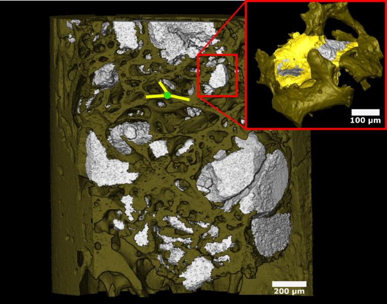
Pak et al. (2020) performed experiments at a SR-µCT beamline to evaluate pore-scale processes in sediments contaminated by trichloroethene (TCE), to optimize field-scale remediation projects using zero-valent iron nanoparticles (nZVI). This work allowed following the TCE degradation at the contamination source and the generation of gaseous products, by performing SR-µCT imaging in time (4D imaging). Pak et al. (2020) observed two main mechanisms of the pore-scale nanoremediation process (Figure 1): (i) gradual in situ degradation of NAPL, through direct reaction with nZVI; and (ii) remobilization of the trapped NAPL by the gas released in the TCE reaction with nZVI, by overcoming capillary forces. Furthermore, it was observed that the gas reduced the relative permeability of water to less than 1%, significantly limiting the migration of the plume in the short term. Therefore, this work brought new perspectives for the potential in situ application of nanoremediation for direct treatment of NAPL sources containing residual phases.
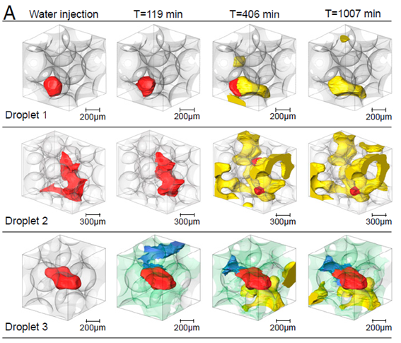
Figure 1. TCE droplets (red) rendered at different time steps. Droplets 1 and 2 are remobilized by the gas phase (yellow). Droplet 3 shows the gradual degradation of TCE and the formation of a water film (blue). The nZVI is rendered in green.
The pre-salt is a set of carbonate rocks formed more than 100 million years ago that constitute important oil reserves. These rocks are located at great depths on the Brazilian coast, below a layer of saline rock at the bottom of the sea. The pre-salt rocks reserves are made up of large accumulations of light oil, of excellent quality, and with high commercial value. Such reserves have made Brazil self-sufficient in terms of oil. As the reservoirs are located thousands at a maximum of 7 km deep, many times, rocks similar to those of the pre-salt layer, which share physicochemical properties with the rocks of interest, are used for studies instead.
First X-ray microtomography image of Sirius’ Mogno beamline. It is a carbonate rock, analogous to the Brazilian pre-salt rocks. The first is a projection and the second is an animation of its segmentation.