CONTACT & STAFF
Facility Tel.: +55 19 3518 2448
Facility E-mail: ema@lnls.br
Coordination: Narcizo M. de S. Neto
Tel.: +55 19 3512 3516
E-mail: narcizo.souza@lnls.br
Click here for more information on this Facility team.


The EMA Beamline (Extreme condition Methods of Analysis) is dedicated to making a difference in the study of materials where high brilliance (high flux up to 1 × 10¹³ photons per second combined with the ability to focus beams as small as 0.1 × 0.1 μm²) is essential, such as in the study of materials under extreme thermodynamic conditions (pressure, temperature, and magnetic field).
This beamline was designed to have two experimental hutches — the microfocus station (operational) and the nanofocus station (under design) — planned to allow great flexibility in combining extreme sample environments (high pressures (P < 800 GPa), high temperatures (T < 5000 K), low temperatures (T > 0.5 K), and high magnetic fields (B < 11 T)) with the most advanced characterization techniques based on synchrotron radiation available worldwide. This includes X-ray absorption spectroscopy, X-ray diffraction, and X-ray scattering techniques. This combination will allow exploring previously inaccessible regions of the P-T-B phase diagram of various materials to solve complex scientific problems at the intersection of such thermodynamic conditions.
In addition, the wide variety of available sample environments and characterization techniques will enable a broad range of studies covering several areas of knowledge, from applied to fundamental science.
More details can be found in: R D dos Reis et al. 2020 J. Phys.: Conf. Ser. 1609 012015
Facility Tel.: +55 19 3518 2448
Facility E-mail: ema@lnls.br
Coordination: Narcizo M. de S. Neto
Tel.: +55 19 3512 3516
E-mail: narcizo.souza@lnls.br
Click here for more information on this Facility team.
The Microfocus station of the EMA beamline began operating in November 2020 for technical and scientific commissioning and is currently operational for standard proposal calls.
| Elemento | Tipo | Posição (m) | Descrição |
|---|---|---|---|
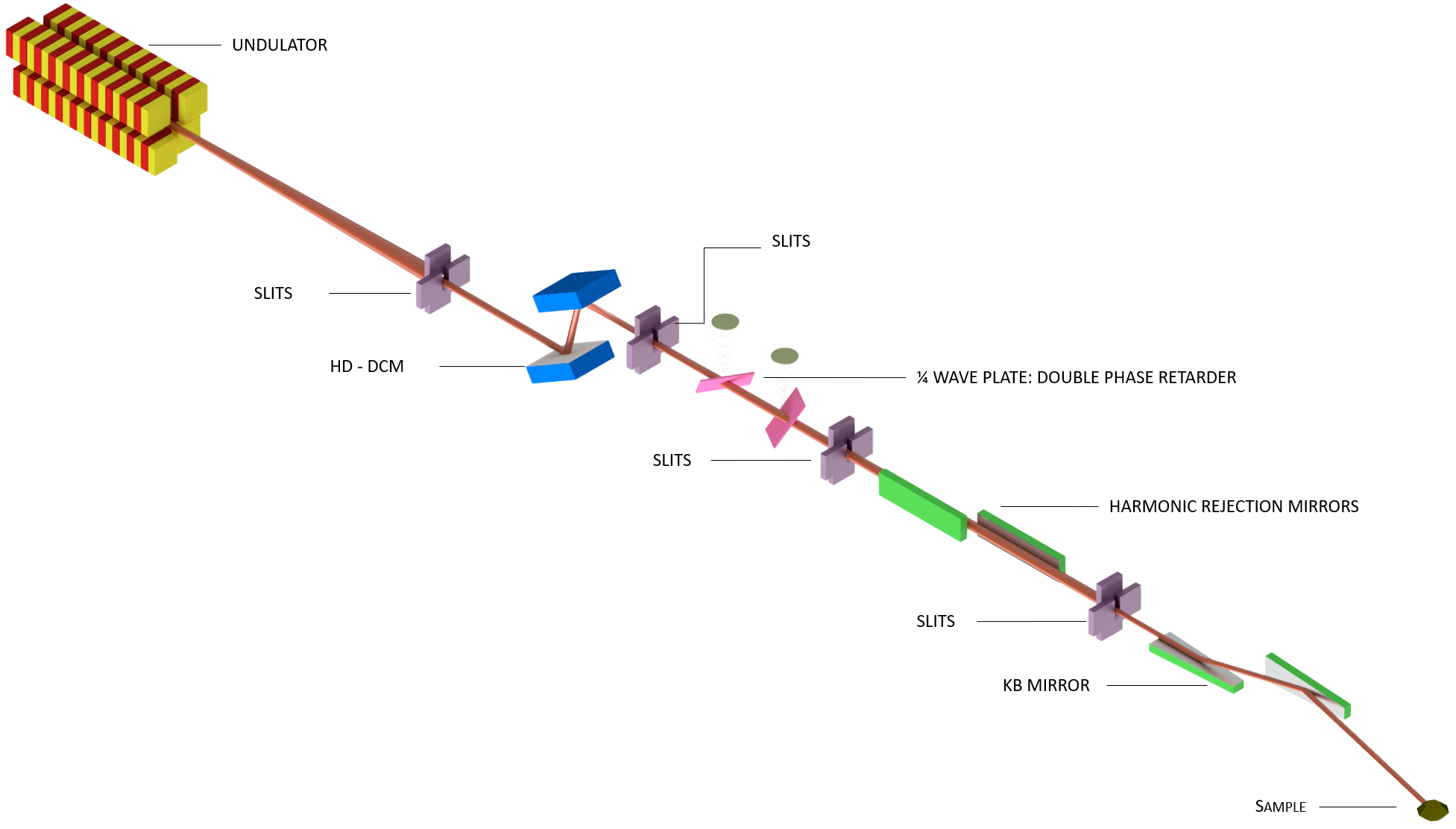
| Source | Undulator | 0.0 | In vacuum undulator, 19 mm period |
| Monochromator | DCM | 28.5 | Vertical bounce, fixed exit. Si 111 and Si 220 |
| ¼ wave plate* | Phase plate | 31.0 | Phase retarder for controlling the polarization |
| KB1 | Mirrors | 44.5 | Bendable vertical and horizontal focusing mirrors for the first experimental hutch |
*A new ¼ wave plate is being developed to increase stability in polarization switching. Its installation on the beamline is planned for the second half of 2026. Therefore, experiments requiring polarization control will not be available during the first half of 2026.
| Parâmetro | Planejado | Condição |
|---|---|---|
| Faixa de energia | 2,7 – 30 keV | 5 – 32 keV |
| Resolução de energia (ΔE/E) | 10−4 – 10−5 | 10−4 – 10−5 |
| Conteúdo de harmônicos | < 10−5 | < 10−5 |
| Varredura de energia | Sim | Sim |
| Tamanho do feixe em 10 keV | 1 x 0,5 μm2 a 50 x 50 μm2 | 1 x 0,5 μm2 a 50 x 50 μm2 |
The EMA beamline was designed to allow a wide variety of experiments, focusing on experiments that explore extreme sample environments of pressure, temperature, and magnetic field. All experimental setups of the beamline have been optimized to accommodate diamond anvil cells (DAC). Experiments without the use of DAC are possible as long as they can be adapted to the same geometry/sample holder. For more details, do not hesitate to contact the EMA beamline team.
When fully commissioned, the EMA beamline will be able to perform the following experimental techniques:
At EMA, the X-ray diffraction (XRD) technique is combined with high pressures to study, precisely and in situ, the structural evolution of materials under compression. Crystalline materials are composed of atoms periodically arranged, which scatter X-rays in well-defined directions, producing diffraction patterns with sharp peaks. The positions of these peaks are directly related to interatomic distances, as described by Bragg’s Law.
The obtained diffraction patterns reveal a series of structural information, such as lattice parameters, crystalline phases, texture (preferred orientations), average grain size, degree of crystallinity, internal stresses, and structural defects. The possibility of performing experiments under high pressures at EMA allows the investigation of how these properties evolve with the contraction of the crystal lattice, being crucial to understanding phenomena such as structural phase transitions, volume collapse, and pressure-induced symmetry modifications.
When combined with a scanning system, it is possible to perform two-dimensional (2D) spatial mappings of the structure, revealing local variations not accessible by conventional techniques with larger beams.
Experiment geometry: Transmission (Debye-Scherrer)
Available detectors: Pimega540D (More details about the detector can be found at https://www.pitec.co/pimega-540d/)
Sample environments: Furnace, Cryostat, Electromagnet, Superconducting magnet, Uniaxial pressure
The technique is used in combination with high pressures to investigate the evolution of electronic and structural properties of materials as the crystal lattice contracts. XAS consists of irradiating the sample with a monochromatic X-ray beam, with the photon absorption measured as a function of the incident photon energy. This technique is element-specific, as it allows selecting a characteristic absorption edge of the element of interest, enabling the study of its local environment, even in complex systems.
The obtained spectra are divided into two regions: XANES (near-edge region), sensitive to the formal oxidation state and coordination geometry of the absorbing atom, and EXAFS (extended fine structure), which provides information about interatomic distances, number of neighbors, and chemical nature of surrounding atoms.
With the use of diamond anvil cells adapted for the EMA beamline, it is possible to perform in situ measurements under pressure, monitoring with high precision the modifications in the XAS spectra as the material is compressed. This approach is essential to understand phenomena such as electronic phase transitions, changes in orbital hybridization, and the evolution of pressure-induced correlated states.
Experiment geometry: Transmission and fluorescence
Available detectors:
The X-ray Magnetic Circular Dichroism (XMCD) technique will be used to study elemental magnetic properties. XMCD is based on the difference in absorption of left- and right-circularly polarized X-rays in the presence of an applied magnetic field, being sensitive to the magnetic moment of atoms of a specific element.
The technique is implemented in the absorption region (XAS), and at EMA it will be applied mainly at the L-edges of rare-earth elements, as well as 4d and 5d transition metals. This energy range allows direct access to the occupied and unoccupied d states of these elements, being ideal for investigating magnetic phenomena associated with orbital hybridization, magnetic anisotropies, and valence transitions.
At EMA, the high intensity and stability of the beam, combined with the ability to perform experiments with circular polarization under extreme conditions such as high pressures, will allow exploring the evolution of elemental magnetism as a function of the modification of the local crystal environment. The use of diamond anvil cells compatible with magnetic fields and with detection in fluorescence geometry will enable in situ XMCD experiments, essential for understanding the coupling between structure and magnetism, electronic transitions, and emergent phenomena such as itinerant ferromagnetism, Kondo states, or exotic magnetic ordering.
Current situation: These techniques are currently under commissioning and, for now, are not available for regular proposals. If you are interested in using them, please contact the beamline staff for more information about the commissioning progress.
At EMA, the techniques of X-ray Ptychography and Bragg Coherent Diffraction Imaging (BCDI) will be explored in combination with high pressures to investigate, with nanometric resolution, the structural evolution of materials as the crystal lattice contracts. Both approaches use coherent X-ray beams, taking advantage of the excellent collimation and brightness provided by Sirius’ fourth-generation synchrotron source.
Ptychography is a lensless imaging technique based on scanning overlapping regions of the sample with a coherent beam, collecting scattering patterns, and subsequent computational reconstruction. By retrieving the amplitude and phase of the scattered waves, this technique allows obtaining two-dimensional images (and three-dimensional ones when combined with tomography) with structural, compositional, and phase contrast, being especially useful for weakly absorbing or heterogeneous materials. In the context of EMA, ptychography will be used to map local modifications of the crystal structure and electronic density induced by compression, revealing variations in morphology, composition, and texture with nanometric resolution.
BCDI, in turn, focuses on reconstructing the electronic density and internal strain field of individual crystals from coherent diffraction patterns collected around a Bragg peak. This technique is especially sensitive to defects, internal stresses, and local lattice distortions, making it ideal for studying structural dynamics and phase transitions under extreme conditions. With the use of diamond anvil cells, EMA will enable BCDI in situ experiments, revealing how strain fields evolve during pressure application — something essential for understanding properties such as mechanical resilience, anisotropic behavior, and structure–function coupling in advanced materials.
Current situation: These techniques are currently under commissioning and, for now, are not available for regular proposals. If you are interested in using them, please contact the beamline staff for more information about the commissioning progress.
The combination of the various techniques available at the EMA beamline — including XAS, XMCD, X-ray diffraction, ptychography, and Bragg Coherent Diffraction Imaging (BCDI) — will enable a comprehensive and correlated analysis of the structural, electronic, and magnetic properties of materials under high pressures. This multimodal approach, with advanced spatial and spectral resolution, will be essential to investigate the evolution of emerging phases, electronic transitions, crystal lattice reorganizations, and the complex interaction between structure and functionality in quantum and multifunctional materials.
The EMA beamline is equipped with several sample environments to serve the community. Below are those currently available. Do not hesitate to contact the beamline team for more details before submitting your proposal.
| Capacilities/Details | Techniques | |
|---|---|---|
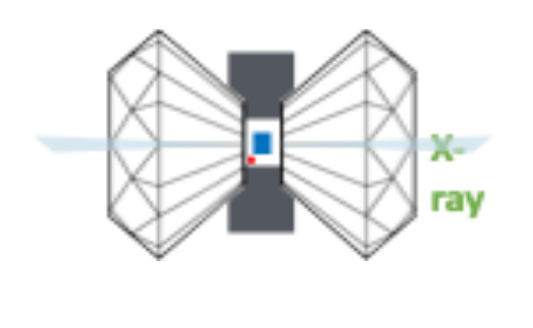
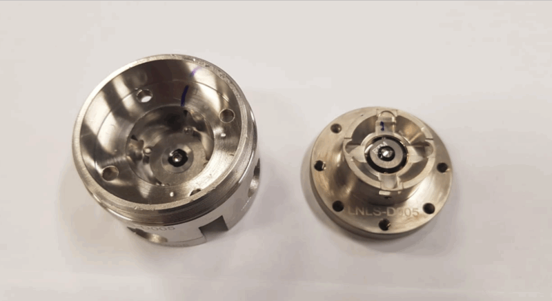
| Diamond anvils cell
|
*Users may use their own pressure cells at the beamline, and their use is encouraged to increase experimental efficiency. Please contact the EMA team so that the necessary adaptations to the sample holders can be made. |
XRD, XAS, XMCD*, Ptycography*, BraggCDI* |
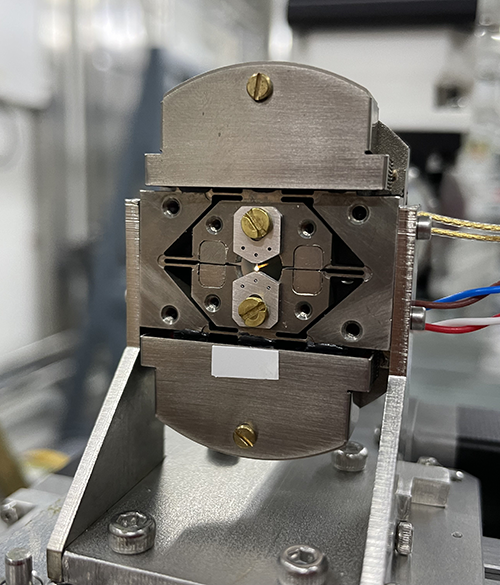
| Uniaxial pressure
|
*Currently, there is only one cell available for experiments, which limits sample exchange. For more information about setup time, please contact the beamline staff. |
XRD, XAS, XMCD*, Ptychography*, BraggCDI* |
| Cryostat
|
|
XRD, XAS, XMCD*, Ptychography*, BraggCDI* |
| Eletromagnet
|
|
XAS, XMCD* |
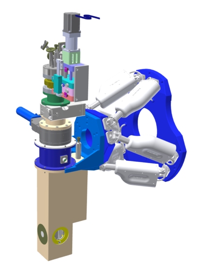
| Superconducting Magnet
|
|
XAS, XRD XMCD*, Ptychography* |
| Furnace
|
|
XRD, XAS, Ptychography* |
| Laser heating
|
|
XRD, XAS, Ptychography* |
* The XMCD, Bragg CDI, and Ptychography experiments are in the commissioning phase and are not available for proposals.